HELP FILE
FOR: DESIGN OF PAD EYE TYPE LIFTINGG
LUGS:
This help file is for both the ENGLISH and the METRIC programs.
DEFINITION:
The design of a lifting lug is made up of four parts; the lug plate, the weld used to connect it to a shell or structure, the bearing stress at the pin hole and the end area of the lug. The design of a lifting lug is very critical and must be done to the latest standards and codes.
For design reference, the program assumes that the lug is in the vertical position with the pin hole at the top. Further, the line of the force is assumed to be in the plane of the strong axis and the angle of the force on the lug is measured from a horizontal reference line thru the center of the pin hole. For example, at zero (0) degrees, the force would be at a right angle to the longitudinal centerline of the lug. At ninety (90) degrees, it would coincide with the longitudinal centerline of the lug. See the pad eye lug drawing below.
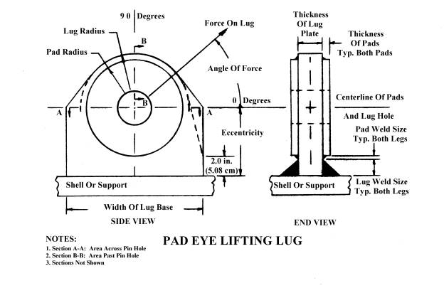
The design of the end area and bearing of the lifting lug are based on the total force on the lug applied in the vertical. Their design is also based on the radius of the lug and not on the width of the lug base. The combined stress of the lug plate and the weld size are calculated from the vertical and horizontal components of the force at the specified angle. These stresses are based on the width of the lug base.
PROGRAM OBJECTIVE:
The objective of this program is to provide a design for the end area of a pad eye type-lifting lug that is efficient and safe. It will also check the bearing stress at the pin hole and the combined stress of the lug plate and the weld. It can also be used to check these same values for an existing lug design. The output information conforms to the requirements of AISC and ASME B30.20.
If the pad eye lug is being used to upend a piece of equipment, the lifting force on the lug increases as the lift angle increases. See example 2 below to see how the program handles a variable force applied to a pad eye lug.
WHAT THE PROGRAM DOES NOT DO:
The program does not:
1. Check the sum of the pad radius + pad weld + lug weld to see if it is less than the eccentricity. The reasoning is that the program user might want to decrease the combined stress of the lug plate and the lug weld size by decreasing the eccentricity. This would be done by cutting a flat segment off the bottom of the pad next to the lug weld. The pad could be cut off as close as 1” (25 mm) to the bottom edge of the lug hole with out structurally affecting the lug design. The pad weld size would then need to be proportionally increased to account for the lose of weld length. See example 3 below.
2. Check the sum of half the width of the lug plus the sling diameter plus 1’’ (2.54 cm) clearance to see if it is less than the distance from the center of the shackle pin to bearing on the bail. If more sling clearance is required, the taper of the lug could start 2” (5.08 cm) above the bottom of the lug base. See the dashed line on the right hand side of the side view on the lug sketch.
3. Compare the required lug weld size to the thickness of shell or support.
This comparison should be made to determine if a lug with a larger cross-sectional area should be used or if a reinforcing pad is required under the lug to lower the weld size.
In any case, the weld size should not exceed the lug thickness or the shell/support thickness.
4. Analysis the local stresses in the shell or support caused by the force on the lug. The local stresses should be analyzed to see if a reinforcing pad is required under the lug to spread out the load, or if the structure needs to be stiffened to prevent over stressing.
These four checks are left up to the program user.
FOR A FIRST TRY IN THE DESIGN OF A LIFTING LUG:
The dimensions of some Crosby shackles are included in the lookup table in the program. Note, all the Crosby shackles are rated in metric tons. Shackle sizes up to 150 metric ton (Te) are model G 2130, sizes over 150 Te are G 2140. The user can select a shackle size from the table based on the force seen by the lug and the dimensions will be imported into the appropriate fields of the program. The dimensions of a lug that has been designed for that shackle size will also be imported into the appropriate fields of the program. If the lug dimensions are not exactly what are required, the user can then fine-tune the design, i.e., increase and/or reduce the force, change the angle of the force, increase the lug width, change the eccentricity, etc, so that it fits the purpose and still meets code.
The lug designs are based on a
force at 60 degrees, Fy = 36 ksi (2.53 Te/cm^2), allowable force on the weld =
14.85 kips/in (1.04 Te/cm) and the I.F. = 1.8
If a shackle size is not listed that the user would like to consider, then the user can click on the SHACKLE button, input the shackle description, for example “Crosby G2130x4.75”, and then input its dimensions and appropriate lug dimensions directly into the fields of the program. The Crosby Group website www.thecrosbygroup.com lists all of their available shackles with dimensions in ENGLISH and METRIC units. For other shackles with dimensions listed in METRIC units, the user will have to refer to other sources.
When the program displays an error message about the lug dimensions, it is sometimes helpful to decrease the force on the lug until the output fields are displayed. This allows the user to see all of the output results and get an idea of which input information to change. As this information is changed, the force on the lug can then be increased to its original value
TOTAL FORCE:
The total force on the lug is input as kips (1 kip = 1,000 lbs.) in the English version and metric tons (Te) in the Metric version.
The Crosby shackles shown in both look up tables are all rated in metric tons, ie the SWL of the Crosby 2130x85 is 85 metric tons. In designing lugs for these shackles, it has been found that in several cases the maximum capacity of the shackle could not be used because the required lug is to wide for the shackle. This is without using a smaller safety factor, using lug material that has a Fy greater than 36 ksi or using a larger angle of the force on the lug, ie 90 degrees. So, to keep things simple, the force on the lugs in the look up tables have been limited to twice the SWL of the shackles as though they were rated in US tons. For example, click on the sample values and note that for a Crosby 2130 x 85 that the force on the lug used is 170 kips for the English version and 77.11 Te for the metric version. The program user is free to design a lug using a force on the lug equal to the SWL of the shackle, which in the above case is 187.39 kips or 85 metric tons. As stated above, to do this, it might be necessary to reduce the impact factor or increase the Fy or use a angle on the lug greater than 60 degrees.
When the program displays error messages about the lug dimensions, it is sometimes helpful to decrease the force on the lug until the output fields are displayed. This allows the user to see all of the output results and get an idea of which input information to change. As this information is changed, the force on the lug can then be increased to its original value.
SIDE LOADING OF THE LUG:
If there is a concern that the lug will be side loaded due to the force not acting in the plane of the strong axis, a gusset can be added to the rear of the lug as shown in the sketch below. This will provide sufficient strength for a side load up to 5 degrees. Note that the pad eye lug program calculates lug properties where:
E = Eccentricity
F = force on the lug
R = radius of the lug
S = Min. thickness of the support base which is equal to or greater than W
T = Thickness of the lug and gusset
w = Pad weld size
W = Lug weld size
The width of the lug is 2*R
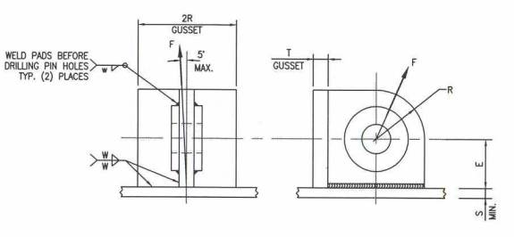
The width of the gusset is a minimum of 2*R
NOTE: Adding a gusset behind the lug plate can also reduce the size of the lug weld W required and/or reduce the local shell stress.
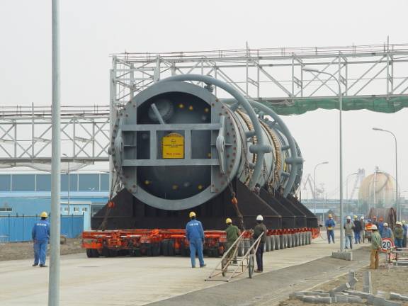
Gussets can also be added to the sides of a pad eye lug to stiffen it against side loading. See the photo in Example 2 below.
IMPACT FACTOR:
A minimum impact factor of 1.80 should be used for new design in order to conform to AISC and ASME B30.20 which limits stresses to .33*Fy. By using 1.80, the allowable stresses can be used as printed in the AISC Manual.
The program allows a variable impact factor to be used so that when checking an existing design, the impact factor can be determined that was used to calculate the stated allowable load for the lifting lug. If the impact factor turns out to be less than 1.8, the program user will then have to make a decision as to the structural integrity of the lug based on its application and the risk involved.
The impact factor is limited to 1.25 or greater.
ANGLE OF THE FORCE ON THE LUG:
With the lifting lug in the vertical position with the pin hole at the top, the angle of the force is measured from a horizontal reference line running through the center of the pin hole. Therefore, if the force is acting at a right angle to the lug, it is at zero degrees. If the force is acting in the vertical direction along the longitudinal centerline of the lug, it is at 90 degrees.
LUG PIN HOLE DIAMETER:
It is recommended that a lug pin hole diameter be used that is 0.13” (0.33 cm) greater than the shackle pin diameter for shackles up to 150 tons (136 Te) and 0.25” (0.64 cm) for shackles sizes larger than that. If a smaller shackle pin diameter is used than the above recommendation, the bearing stresses will be higher. If a larger shackle pin diameter is used than the above recommendation, the pin might not fit up with the hole in the lug due to manufacturer and fabrication tolerances.
For the first try in the design of a lifting lug, the user can select the appropriate shackle from the lookup table in the program based on the force on the lug. The dimensions of the shackle and a pre-designed lug will automatically be entered into the appropriate input fields in the program.
LUG RADIUS:
After the user enters all of the input values and clicks on calculate, the program will check to make sure that the “lug radius” is equal to or greater than the output value for the “maximum effective lug radius”. If the lug radius is smaller, the program will prompt the user to enter a larger radius.
NOTE:
1. If the program allowed a lug radius to be used that is smaller than the maximum effective lug radius, then the “maximum allowable end area” would be smaller than the area required past the pin hole.
2. “The maximum allowable end area” is calculated using the “maximum effective lug radius”, so using a “lug radius” that is larger than the maximum effective lug radius will not result in an increase in the maximum allowable end area, only an increase in the actual end area.
3. The
maximum effective lug radius is a requirement per AISC to prevent the design of
the lug beyond the pin hole from being long and thin, ie subject to buckling.
LUG PLATE THICKNESS:
The selection of the thickness of the lug plate should be limited to those sizes available. Installing pads is an additional cost, so generally it is more economical to use a thicker lug plate whenever possible in lieu of using pads.
It is not recommended to weld two lug plates together to get the desired lug plate thickness.
WIDTH OF THE LUG PLATE AT THE BASE:
Pad eye lug plate dimensions vary from lug to lug, depending on the designer’s criteria and the application. The most common type of pad eye lug is where the width of the lug plate equals two times the radius of the lug and the distance from the base of the lug to the pin hole (the eccentricity) is determined by the radius of the pads, the lug weld size, the pad weld size, the radius of the shackle eyes, an obstruction on the structure, etc.
Some lugs are wider at the base than two times the lug radius, due to the need for additional weld length, more bending strength, etc. The lugs are connected to the shell or structure with two butt welds.
No matter what the shape of the lug is, the design of the end area is based on the lug radius and not on the width of the base. This is why most designs are very conservative concerning the area of the lug across the pin hole and the most important consideration is the area past the pin hole. See sections A-A and B-B on the lug sketch.
ECCENTRICITY:
The eccentricity is used to calculate the bending in the lug plate due to the horizontal component of the force. The program also uses it to check to make sure that the eccentricity is greater than the sum of the shackle eye radius plus the actual lug weld.
NOTE: Increasing the eccentricity to satisfy the above check will increase both the combined stress and lug weld size. Therefore the eccentricity will probably need to be increased in increments of 0.25” to 0.5” (0.64 cm to 1.27 cm).
If the angle of the force on the lug is increased to say 90 degrees, then the lug weld size will decrease and the eccentricity can be decreased accordingly.
LUG PADS:
Pads are usually designed and welded to the plate lug when the actual bearing stress is greater than the allowable bearing stress. Some times they are used to increase both the end area and to reduce the bearing stress.
The pads should be welded to the lug plate and then the pin hole line bored so that even bearing is obtained between the pads and the lug plate. There is a DIN standard that allows the I.D. of the pad holes to be larger than the I.D. of the lug hole. Using pads of this design will provide more end area but will do nothing for bearing.
In order to allow sufficient room for the weld between the lug and the pad, it is recommended that for an initial try the user should use a pad radius 0.5 in (1.27 cm) smaller than the lug radius. The program will check to see if the sum of the pad radius plus the pad weld is greater than the lug radius. In looking at the output information, the user can then increase the pad radius if there is more than enough room for the pad weld.
INSIDE WIDTH
OF THE SHACKLE:
It is recommended that the sum of the thickness of the lug plate plus the thickness of the pads plus 0.25 in. (0.64 cm) clearance be equal to or smaller than the actual inside width of the shackle measured at the pin. The program will check this clearance. The user can fool the program and decrease the 0.25 in. (0.64 cm) clearance to say 0.15 in. (0.38 cm) by entering the shackle width 0.10 in. (0.25 cm) larger than it actually is.
LUG PAD WELDS:
The weld sizes for the pads in this program are based on using LH 60 rod and a force on the weld of 9.6 kips/in
EXAMPLE 1: Using the program with English Units.
The “sample values” button at the bottom of the input screen contains input for a typical Pad eye problem where the force on the lug is at a specific angle. By clicking on “sample values” the input values are shown with the output values blank. By then clicking on “calculate”, both the input and output values are shown.
EXAMPLE 2: Using the program with English Units.
REACTOR
WITH TWO PAD EYE TYPE LIFTING LUGS
Often, one or two pad eye lugs are welded to the head of a vessel or to the top of a piece of equipment such as a cold box or reactor and are then used to upend the piece of equipment from the horizontal to the vertical, similar to the photo above. In this case, the force on the lugs increase as the lift angle of the equipment increases. The following procedure shows how to calculate the bearing and end area of the lug, the combined stress on the lug plate and weld for this type of lift. The photo shows two pad eye lugs being used to lift a 770-ton reactor. For this example, assume that the force on each pad eye lug will be 170 kips at the set position.
It requires two runs of the pad eye program to determine the required output values. In order to simplify data entry, use the sample input values from example 1 where the force on the lug is 170 kips.
For the first run of the pad eye program, click on the sample values and change the lift angle from 60 degrees to 90 degrees. Leave the 170 kips as the force on the lug because this value will be the load on the lug with the vessel in the vertical position. Note that the combined stress check on the lug plate changed from 0.96 to 0.40 and the weld size changed from 1.78 in to 0.74 in. The bearing and the lug calculations remain the same. Make a printout of this run, but note on it that the values for the combined stress and lug weld size are not applicable and their maximum values will be determined by the second run.
To make the second run of the pad eye program, the vertical force on the lug needs to be known for equipment lift angles from 0 degrees through about 35 degrees. Somewhere in this range, generally around 20 degrees, will be the worst case for combined stress on the lug plate and the weld when up ending a vertical vessel. Remember that 0 degrees for the lug is where the vessel is in the horizontal position at 0 degrees lift angle. The user can calculate the forces by hand or go to the upending forces program in the same section of the website as this program, click on the sample values and change the total weight from 1120 kips to 170 kips to match the sample weight shown in example 1 above. Leave the rest of the input fields as they are as the assumption can be made that they are the dimensions for the vessel being upended in this example. Run the program and make a printout similar to the one below.
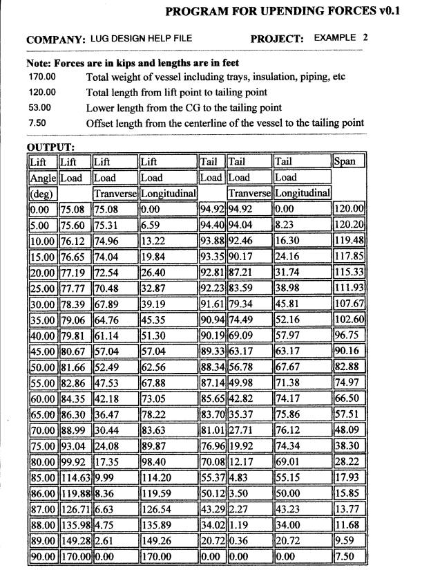
Several trial runs of the pad eye program are required to determine the worst-case lift angle, from which the second final pad eye lug run will be selected. First, click on the sample values and change the lift angle to 0 degrees and the force on the lug to 75.08 kips. This information came from the first row on the left in the printout above from the upending program. Note that the combined stress on the lug plate is now 0.54 and the weld size is 1.03 in. Disregard the output information on the bearing and the end area because of the reduced weight being used of 75.08 kips.
Make a similar trial run for each lift angle up thru 35 degrees and make a note of the combined stress value and the weld size. Note that the for the lift angle of 20 degrees and a force of 77.19 kips that the combined stress is 0.58 and the weld size required is 1.10 in. This is the lift angle for the worst case for combined stress for the lug plate and the weld for this lug. Make a printout of this run where the lift angle is 20 degrees and the force on the lug is 77.19 kips. Use this run as your second pad eye lug run. Again, mark out the information on the bearing and end area as not being applicable for this lift angle and load. Note that the difference between the combined stress and the weld required at initial pick (when the vessel is in the horizontal at 0 degrees lift angle) and when it is at 20 degrees is approximately 7 %.
To recap, the bearing and the end area of the lug were calculated from the first run where the maximum force of 170 kips occurred when the vessel is in the vertical. The maximum combined stress for the lug plate and the weld were calculated from the second run where the force of 77.19 kips occurred when the vessel is at a lift angle of 20 degrees. From these two runs, it can be seen that the lug designed by the sample values for a fixed force of 170 kips on the lug at 60 degrees is also adequate to be used to up end the vessel in this example.
Just for information, note on the
printout of the upending forces, that the maximum longitudinal tail load occurs
at 70 degrees at 76.12 kips. If the
forces on the tail lug were being analyzed, this would be the angle of maximum
combined stress for the tail lug plate and weld, the opposite lift angle
from the lifting lug.
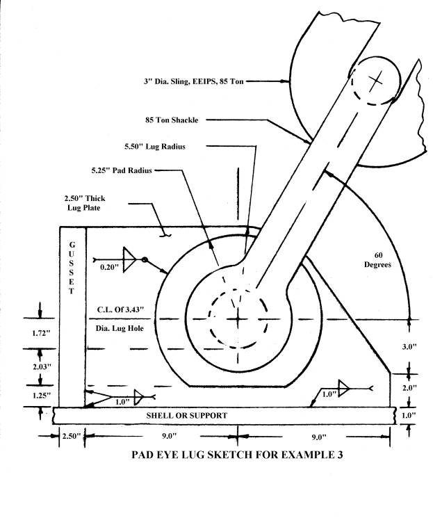
EXAMPLE 3: Using the program with English Units.
This example is to show how the combined stress of the lug plate and the lug weld size can be reduced by lowering the eccentricity. This can be done by cutting off the bottom segment of the lug pads. To simplify the calculations, the sample values in the program will be used as the basis for this example. The sample input values for the program yield a combined stress value of 0.96 and a lug weld size of 1.78”. As the lug in this example must have a maximum width of 18.0” and will be welded to a shell that has a thickness of 1.0”, the weld size must be reduced to 1.0”. To reduce the lug weld size, first increase the input value of the lug plate width from 14.0” to 18.0”. This will provide more weld length, thus decreasing the weld size. Click on the calculate button and note that the combined stress value is 0.64 and the weld size is now 1.20”. Still not low enough. Now decrease the eccentricity from 7.0” to 5.0”. 5.0” was chosen because it is larger than the sum of the 3.25” radius of the eye of the shackle plus the required lug weld size of 1.0”, which equals 4.25”. This will reduce the moment on the weld, thus decreasing the weld size even further. Calculate and notice that the combined stress value is 0.53 and the lug weld size is now 1.01, close enough for bridge work. Just for fun, decrease the eccentricity to 4.20 and note that the combined stress value is 0.49, the lug weld size is 0.94” and the pad weld size is 0.19”. As the pad weld size is not the estimated 0.5” per the sample value, increase the lug pad radius to 5.25 to get as much end area past the pin hole as possible. Calculate and note that the pad weld size is now 0.18 and the end area past the pin hole has gone from 14.07 sq. in. up to 14.45 sq. in.
Because the weld length for the pad has been decreased by more than 1.0” due to cutting off the bottom segment, the pad weld size must be increased proportionally to 0.20”.
Refer to the sketch below to see the final configuration and dimensions of the lug. Note on the left side that the three vertical dimensions add up to the eccentricity of 5.0”. 5.0” minus half of the hole diameter of 1.72” minus the estimated pad weld size of 0.25” minus the lug weld sizes of 1.0” equal 2.03” which is the distance from the bottom of the lug hole down to the bottom of the cropped pad. It is recommended that this distance be at least 1.0”, so the pad could be cropped a little more if desired. In this case, the minimum distance would be 1.28” and then the bottom of the shackle eye would start to interfere with the lug weld.
EXAMPLE 4: Using the program with Metric Units.
The “sample values” button at the bottom of the input screen contains input for a typical Pad eye problem. By clicking on “sample values” the input values are shown with the output values blank. By then clicking on “calculate”, both the input and output values are shown.
EXAMPLE 5: Using the program with Metric Units.
Often, one or two pad eye lugs are welded to the head of a vessel or to the top of a piece of equipment such as a cold box and are then used to upend the piece of equipment from the horizontal to the vertical. In this case, the forces on the lugs increase as the lift angle of the equipment increases. The following procedure shows how to calculate the bearing and end area of the lug, the combined stress on the lug plate and weld for this type of lift. For this example, assume that the force on each pad eye lug will be 77.11 Te.
It requires two runs of the pad eye program to determine the required output values. In order to simplify data entry, use the sample input values from example 3 where the final set load is 77.11Te on the lug.
For the first run of the pad eye program, click on the sample values and change the lift angle from 60 degrees to 90 degrees. Leave the 77.11 Te as the force on the lug because this value will be the load on the lug with the vessel in the vertical position. Note that the combined stress check on the lug plate changed from 0.96 to 0.40 and the weld size changed from 4.54 cm to 1.88 cm. The bearing and the lug calculations remain the same. Make a printout of this run, but note on it that the values for the combined stress and lug weld size are not applicable and the maximum values will be determined by the second run.
To make the second run of the pad eye program, the vertical force on the lug needs to be known for lift angles from 0 degrees through about 35 degrees. Somewhere in this range, generally around 20 degrees, will be the worst case for combined stress on the lug plate and the weld when up ending a vessel. Remember that 0 degrees for the lug is also where the vessel is in the horizontal position at 0 degrees lift angle. The user can calculate the forces by hand or go to the upending forces program in the same section of the website as this program, click on the sample values, click on the METRIC radio button and change the total weight from 1120 kips to 77.11 Te to match the sample weight shown in example 3 above. Also, change the dimensions in the sample values from feet to meters as the assumption can be made that they are the dimensions for the vessel being upended in this example. Run the program and make a printout similar to the one below.
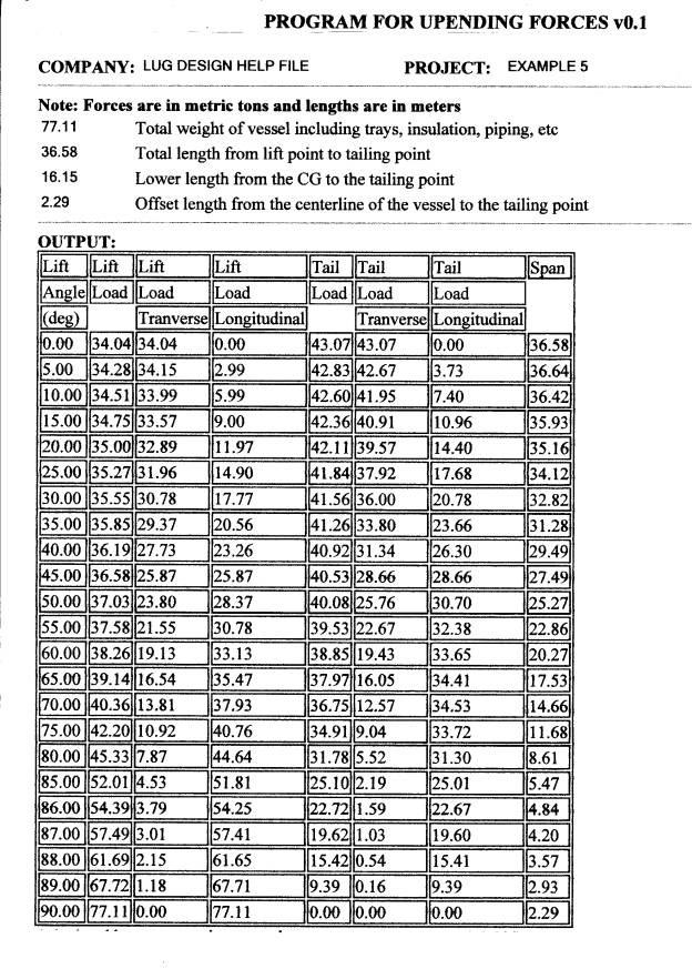
Several trial runs of the pad eye program are required to determine the worst-case lift angle, from which the second final pad eye lug run will be selected. First, click on the sample values and change the lift angle to 0 degrees and the force on the lug to 34.04 Te. This information came from the first row on the left in the printout above from the upending program. Note that the combined stress on the lug plate for this run is 0.54 and the weld size is 2.62 cm. Disregard the output information on the bearing and the end area because of the reduced weight being used of 34.04 Te.
Make a similar trial run for each lift angle up thru 35 degrees and make a note of the combined stress value and the weld size. Note that the for the lift angle of 20 degrees and a force of 35.00 Te that the combined stress is 0.58 and the weld size required is 2.81 cm. This is the lift angle for the worst case for combined stress for the lug plate and the weld for this lug. Make a printout of this run where the lift angle is 20 degrees and the force is 35 Te. Use this run as your second pad eye lug run. Again, mark out the information on the bearing and end area as not being applicable for this lift angle and load. Note that the difference between the combined stress and the weld required at initial pick (when the vessel is in the horizontal at 0 degrees lift angle) and when it is at 20 degrees is approximately 7 %.
To recap, the bearing and the end area of the lug were calculated from the first run where the maximum force of 77.11 Te occurred when the vessel is in the vertical. The maximum combined stress for the lug plate and the weld were calculated from the second run where the vessel is at a lift angle of 20 degrees and the force of 35.00 Te occurred.
Just for information, note on the printout of the upending forces, that the maximum longitudinal tail load occurs at 70 degrees at 34.53 Te. If the forces on the tail lug were being analyzed, this would be the angle of maximum combined stress for the tail lug plate and weld, the opposite lift angle from the lifting lug.
END OF HELP FILE