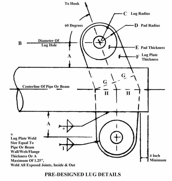
PRE-DESIGNED LIFTING LUGS
Information in the sketch and the table below can help expedite the spreader bar design, ie, the “A” distance for a selected shackle when added to 0.5*O.D. of the pipe will determine the offset distance from the centerline of the pipe to the centerline of the top lifting lugs holes. As soon as the spreader bar design is complete, the lug details can be used from the table for lug fabrication. The fabricated lugs can then be welded to the spreader bar.
|
Crosby Metric Shackles G-2130 SWL |
A In. |
B In. |
C In. |
D In. |
E In. |
F In. |
G In. |
H In. |
I In. |
Fy ksi |
|
|
|
|
|
|
|
|
|
|
|
|
|
8.5 Te |
2.75 |
1.28 |
3.00 |
0.00 |
0.00 |
1.25 |
3.00 |
3.46 |
0.00 |
36.00 |
|
18.75 Kips |
|
|
|
|
|
|
|
|
|
|
|
12 Te |
3.00 |
1.53 |
3.00 |
0.00 |
0.00 |
1.50 |
3.00 |
3.46 |
0.00 |
36.00 |
|
26.47 Kips |
|
|
|
|
|
|
|
|
|
|
|
17 Te |
3.38 |
1.79 |
3.50 |
0.00 |
0.00 |
1.50 |
3.50 |
4.04 |
0.00 |
36.00 |
|
37.50 Kips |
|
|
|
|
|
|
|
|
|
|
|
25 Te |
3.63 |
2.17 |
4.00 |
0.00 |
0.00 |
2.00 |
4.00 |
4.62 |
0.00 |
36.00 |
|
55.15 Kips |
|
|
|
|
|
|
|
|
|
|
|
35 Te |
4.00 |
2.43 |
4.00 |
0.00 |
0.00 |
2.25 |
4.0 |
4.62 |
0.00 |
36.00 |
|
77.21 Kips |
|
|
|
|
|
|
|
|
|
|
|
55 Te |
6.00 |
2.93 |
5.00 |
4.50 |
0.50 |
2.00 |
5.00 |
5.77 |
0.13 |
36.00 |
|
121.33 Kips |
|
|
|
|
|
|
|
|
|
|
|
85 Te |
7.00 |
3.43 |
5.50 |
5.00 |
0.75 |
2.50 |
5.50 |
6.35 |
0.21 |
36.00 |
|
187.51 Kips |
|
|
|
|
|
|
|
|
|
|
|
120 Te |
8.00 |
3.89 |
6.50 |
6.00 |
1.00 |
3.00 |
6.50 |
7.51 |
0.26 |
36.00 |
|
264/72 Kips |
|
|
|
|
|
|
|
|
|
|
|
150 Te |
8.50 |
4.39 |
7.00 |
6.50 |
1.00 |
3.00 |
7.00 |
8.08 |
0.30 |
50.00 |
|
330.90 Kips |
|
|
|
|
|
|
|
|
|
|
|
|
|
|
|
|
|
|
|
|
|
|
|
G-2140 SWL |
|
|
|
|
|
|
|
|
|
|
|
|
|
|
|
|
|
|
|
|
|
|
|
200 Te |
10.25 |
5.00 |
8.00 |
7.50 |
1.50 |
3.50 |
8.00 |
9.24 |
0.41 |
36.00 |
|
441.20 Kips |
|
|
|
|
|
|
|
|
|
|
|
250 Te |
11.00 |
5.25 |
8.50 |
8.00 |
1.75 |
4.00 |
8.50 |
9.81 |
0.48 |
36.00 |
|
551.50 Kips |
|
|
|
|
|
|
|
|
|
|
|
300 Te |
12.25 |
6.25 |
10.00 |
9.25 |
2.00 |
4.00 |
10.00 |
11.55 |
0.53 |
36.00 |
|
661.80 Kips |
|
|
|
|
|
|
|
|
|
|
|
400 Te |
14.00 |
7.25 |
11.50 |
10.75 |
2.00 |
4.00 |
11.50 |
13.28 |
0.61 |
50.00 |
|
882.40 Kips |
|
|
|
|
|
|
|
|
|
|
|
|
|
|
|
|
|
|
|
|
|
|
|
G-2160 SWL |
|
|
|
|
|
|
|
|
|
|
|
|
|
|
|
|
|
|
|
|
|
|
|
500 Te |
14.00 |
7.34 |
11.50 |
10.75 |
2.25 |
5.00 |
11.50 |
13.28 |
0.73 |
50.00 |
|
1,1103.00 Kips |
|
|
|
|
|
|
|
|
|
|
|
600 Te |
15.00 |
8.12 |
13.00 |
12.00 |
2.50 |
5.00 |
13.00 |
15.01 |
0.82 |
50.00 |
|
1,323.60 Kips |
|
|
|
|
|
|
|
|
|
|
DESIGN REQUIREMENTS:
The pre-designed lifting lugs in the table can be used if the designer of the spreader bar program will:
1. Use lift sling angles equal to 60 degrees.
2. Design the spreader bar for zero moment in the pipe due to the influence of the lift slings. This is where the line of force from the inclined portion of the lift slings intersects the line of force from the vertical portion of the lift slings at the centerline of the pipe or beam. To design the spreader bar for zero moment, make a run where the output fields show some values other than “ERROR”. The user might have to reduce the load to be lifted in order to clear the output fields of the “ERROR” message. Then re-enter the values from the first two output fields back into the appropriate input fields. See the examples below.
SELECTING A SHACKLE SIZE AND A PRE-DESIGNED LUG:
1. Determine the tension in the inclined portion of each lift sling by multiplying the load to be lifted by 0.5 * 1.15. The 1.15 is the approximate increase in tension of a sling at 60 degrees.
2. Go to the lug table above and select a shackle that has a SWL greater than the tension in the inclined portion of the lift slings.
3. Make a note of the “A” distance for this pre-designed lifting lug.
4. Add the “A” distance to 0.5*O.D. of the pipe that will be considered in the spreader bar design to get the offset distance from the centerline of the spreader bar to the centerline of the lifting lugs for this lug design.
SPREADER BAR DESIGN:
1. Example 1: A total load of 200 kips must be lifted with a 20’ long spreader bar. The steps to design this bar using the spreader bar program are:
a. Estimate the approximate tension for each sling = total load to be lifted in kips*0.5*1.15 = 115 kips
b. Select a 55 Te shackle from the lug table, which has a SWL greater than the above tension, ie, 121.33 kips > 115 kips
c. The “A” distance for this shackle is 6.0”.
d. Try using an 8” x 0.322” wall pipe. Add the “A” distance to 0.5*O.D. of the pipe. Therefore, the offset distance from the centerline of the pipe to the centerline of the top lifting lugs is 6”+8.63”/2 = 10.32”
e. Enter 10 kips for the total load, a reduction from the 200 kips
f. Enter 120” for the horizontal distances from all four lugs to the CG, as the CG is centered between the lugs
g. Enter 10.32” for the offset distance
h. Enter 259.54” for the OAL of the spreader bar, ie, 240” + 9.77” for each end, where the 9.77” is made up of H = 5.77” + 4” from the edge of the lug
i. Calculate and note that the moment due to the offset lugs = 29.79 k-in.
j. Also note that the first two output fields show a value of 114.04”
k. Re-enter these two values in the appropriate input fields
l. Calculate and note that the moment due to the offset lugs is now = -0.01 k-in and the Combined Stress Check (CSC) is only 0.14
m. Change the total load to 200 kips, calculate and note that the CSC is now 0.99
The spreader bar design is acceptable and the pre-designed lifting lug using a 55 Te shackle can be used. The designer just has to compute the missing dimensions of the lifting lug plates from center of top lug holes to bottom lug holes along the centerline of the lug plate, have two lug plates fabricated per the lug details in the table, one for each end of the spreader bar, and weld them to the spreader bar.
1a. If the CSC had been greater than 1.0 or a smaller CSC was desired, a 12”x 0.375” wall pipe could have been considered by repeating steps 3c thru 3m. ie:
a. Enter 10 kips for the load
b. Enter 120” for the horizontal distances from the CG to all four lugs
c. Enter 6” + 12.75”/2 = 12.38” for the offset distance
d. Calculate and note that the moment due to the offset lugs = 35.74 k-in.
e. Also note that the first two output fields = 112.85”
f. Enter the 112.85” back in to the appropriate input fields
g. Calculate and note the moment due to the offset lugs is now = -0.01 and that the CSC = 0.09
h. Enter 200 kips for the load and calculate
i. Note that the CSC = 0.47 The spreader bar design is acceptable
2. Example 2: A 20’ long spreader bar needs to lift 1,500 kips.
a. The tension in each sling will be approximately 862 kips
b. From the lug table, select a 400 Te shackle with SWL = 882 kips
c. The “A” distance = 14”.
d. As a first try, use a 30”x 0.375” wall pipe and the offset distance will be 15” + 14”” = 29”
e. Enter 10 kips as the load
f. Enter 24” for the horizontal distance from prong to prong on a duplex hook. A crane with the capacity to lift 1500 kips would have a duplex hook
g. Enter 120” for the distances from all the lugs to the CG
h. Enter the offset distance as 29”
i. Enter 274.56” for the OAL, where H = 13.28”
j. Calculate and note that the first two output fields = 103.26”. Enter them back into the appropriate input fields
k. Change the load to 1,500 kips and calculate
l. Note the “ERROR” message that says the CSC = 1.13
2a. Try a 36”x 0.375” wall pipe where the offset distance now = 18”+14” = 32”
a. Enter the load as 10 kips
b. Enter 120” for the distances from all the lugs to the CG
c. Enter the offset distance as 32”
d. Calculate and note that the first two output fields = 101.52”. Enter them back into the appropriate input fields
e. Change the load to 1,500 kips and calculate
f. Note that the CSC = 0.92 Spreader bar design is acceptable
2b. As an exercise, the reader can determine for himself that an 18”x 1.375” wall pipe can be used with a resulting CSC = 0.63. This spreader bar design is also acceptable.
COMMENTS:
1. Always try to use a pipe with a standard (Std) wall thickness if possible, as it is cheaper and more readily available than thicker wall pipe. The smallest wall thickness for all pipes listed in the look up table in the program up to and including a 26” pipe is a Std wall thickness. 30” Pipe and above do not have a Std rating.
2. If the lift sling angles are different than 60 degrees, say 70 degrees, the design information in the table is still valid. The only change is that the designer must compute a new “H” before fabricating the lug plates. This is still true if the CG is off center and the two lift sling angles are not the same. In this case, the “H” would be different for both ends of the spreader bar.
3. To connect the lifting lug plates to a pipe spreader bar, use a metal saw and slot both ends of the pipe, top and bottom, so that there will be a tight fit between the lug plates and the slots. Slip the lug plates into the slots and weld them to the pipe per the weld instruction on the sketch. Weld the slot material back in the slots in the pipe.
4. To connect the lifting lug plates to a beam spreader bar, use a metal saw and slot both the top and bottom flanges on both ends of the beam so that there will be a tight fit between the lug plates and the flanges. Trim the web to fit the lifting lug plates. Slip the lug plates into the slots and weld them to the web and the flanges per the weld instructions on the sketch. Trim the web material to fit the outboard edge of the lug plates. Weld it to the lug plates and the flanges. Weld the slot material back in the slots of the flanges.
5. It is recommended that the designer analyze the weld connections between the lug plates and a Std wall or thin wall pipe spreader bar, that is lifting a heavy load, to make sure that the compression load from the lift slings does not cause the lug plates to overstress the pipe in compression and the welds in shear. If necessary, weld doubler pads to the pipe around the lifting lugs to provide additional weld length/cross-section. This is usually cheaper than using the same diameter of pipe with a larger wall thickness.
6. The pre-designed lifting lugs have been design for the SWL of the Crosby metric shackles, ie, the 8.5 Te shackle has been designed for 18.75 kips.
7. Note that the lug plate and pads for the 150 Te, 400 Te, 500 Te and 600 Te shackles required a Fy of 50 ksi in order to be designed for the full SWL of the shackles.
8. The pre-designed lifting lugs have been design for a straight pull, ie, the force on the lug coinciding with its longitudinal centerline.
9. Pipe diameters of 14” and larger have the same O.D. as the pipe designation, ie, the O.D. for a 14” diameter pipe is 14”.
10. The length of a spreader bar can be changed by cutting out or adding a section of pipe that has the same wall thickness and Fy as the original. The only requirements are:
a. The connecting weld(s) must be a full penetration weld made and stamped by a certified welder
b. The weld must be x-rayed and approved as a sound weld
c. The two sections of pipe must be laid in a jig so that the straightness for the total length is equal to that of a new pipe
d. As a safety precaution, do not make the splice at the center of the pipe where the moment is greatest
END OF PROCEDURE