-
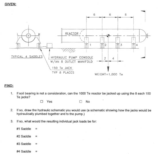
Yes, the 1000 Te reactor can be safely jacked up using eight 150 Te hydraulic jacks. In order to be able to jack up the reactor, the eight jacks must be plumbed into hydraulic groups such that no individual jack can be over loaded. The hydraulic pump is equipped with a manifold that has 8 outlets so one way to plumb the jacks would be to run individual hoses from the manifold to each of the eight jacks. The only problem with an eight point support is that without a computerized console, it is almost impossible to keep from overloading any one jack during the jacking process. As most jobs would not have a computerized pumping console available, this method will not be considered as feasible in this quiz.
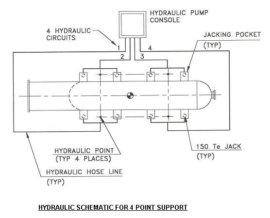
Another way would be to plumb the jacks into a four point hydraulic support system with two jacks making up each hydraulic group. The problem with this method is that unless the jacks are supported on a very firm footing (say on a deep concrete foundation or on large load spreaders), settlement of one or two jacks in a hydraulic group will cause other jack groups to become overloaded, due to the table leg effect where one leg shorter than the other three will overload the two diagonal legs. Also the table leg effect can occur when jacking a load up (even without differential settlement between jacks) if the pressure in each hydraulic group is not monitored very closely. The bottom figure on page three shows a graphic schematic for a four point support system. Note that the hydraulic points (centroids) for hydraulic groups (circuits) 1 & 2 are located 2 + 3 = 5 units left of the center of gravity (CG) and the hydraulic point for circuits 3 & 4 are located 4 + 3 = 7 units right of the CG. Therefore, the individual load per jack for saddles 1 & 2 is 1000 Te * 7 units / (12 units * 4 jacks) = 145.83 Te. The individual load per jack for saddles 3 & 4 is 1000 Te * 5 units / (12 units * 4 jacks) = 104.17 Te.
The method most often used to jack up a heavy load is the three point hydraulic support system. This method gives the user the ability to raise or lower either end of a load such as a reactor or to roll it from side to side if desired, providing that in doing so none of the jack rams bottom out while they are extending or retracting. This means that differential settlement of the jacks is not a problem with this method. Refer to the top figure in the sketch below which shows a schematic for a three point hydraulic support system. Note that jacks L1+ L2 make up circuit 1, jacks R1 + R2 make up circuit 2 and jacks L3 +L4 + R3 + R4 make up circuit 3. The centroids or hydraulic points of circuits 1 & 2 are both located 5 units left of the CG and the centroid of circuit 3 is located 7 units right of the CG. This makes the reactor very stable during jacking because the CG is located closer to the two hydraulic points in circuits 1 & 2 that control the roll than it is to the third hydraulic point that controls elevation. This eliminates the wheel borrow effect where a load that is located over the front tire rather than back closer to the two handle bars causes the wheel borrow is be very unstable and wants to tip over. Based on the above analogy, the user should always try to keep the CG closer to the base of the stability triangle than to it's top. The stability triangle is formed by connecting the hydraulic points of the three hydraulic groups with lines and the CG must always stay inside of these lines for the load to be stable. The three point hydraulic support system is similar to the four point system except that circuits 3 & 4 have been connected together to form circuit 3. Therefore, the individual jack loads for each saddle are the same, namely 145.83 Te for saddles 1 & 2, and 104.17 Te for saddles 3 & 4.
Note that another way to make a three point hydraulic support system for this example is to plumb jacks L1 + L2 + L3 into circuit 1, plumb jacks R1 + R2 + R3 into circuit 2, and plumb jacks L4 + R4 into circuit 3. This will lower the individual jack loads to 138.89 Te for the jacks at saddles 1, 2 & 3, and 83.33 Te for the jacks at saddle 4. The down side is that the CG of the reactor will then be located 2 units from the base of the stability triangle. Depending on the jacking requirements, the CG being that close to the base of the stability triangle may not provide enough stability for tipping in the longitudinal direction of the reactor. It is left to the reader to draw the schematic for the above three point support system and to verify the individual jack loads.
In general, it is a good rigging practice to design jack loads for a maximum of 50 to 60% of the jack's capacity. The high jack loads in this quiz were only used to make the quiz more interesting.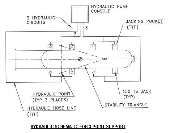
Maximum Reach Enterprises