TIPS FOR HEAVY LIFTING
AND
RIGGING ENGINEERING
Posted March 2003
This section contains tips and recommendations on heavy lifting and rigging engineering. I am a firm believer that the better we communicate lessons learned, unique ideas and good rigging practices to others, the safer the rigging industry will become. The material presented here has served me well during the years I worked as a Crane Operator, Rigging Superintendent and Rigging Engineer. Readers are encouraged to submit tips, suggestions, comments, recommendations, or requests for more information about a certain item. Credit for tips or recommendations submitted will be given unless instructed not to. I reserve editorial rights on what material will be used.
The following topics have been address so far. Others will be added as time allows or on special request. The topics under CRANES and RIGGING ENGINEERING are in alphabetical order but the items with in a topic are not. New items will be added to the bottom of a particular topic.
TABLE OF CONTENTS
CRANES
INSPECTION:
1. CRANE INSPECTION
AND LOAD TEST PROCEDURE FOR
CONVENTIONAL
CRAWLER AND TRUCK CRANES
Every crane should be subjected to
two types of inspections:
a. A
maintenance inspection
b. A
safety and operational inspection
The maintenance inspection is geared
more to preventative maintenance and identifying those items requiring repairs
that will prevent the crane from being in a like new condition or from
operating correctly, such as oxidized or cracking paint, sheet metal damage,
track pad wear, track roller wear, rubber tire wear, oil levels, oil changes,
etc. The Equipment Superintendent or
his representative usually performs this inspection.
The safety and operational
inspection, on the other hand is more concerned with identifying those items
that will either stop a lift during the middle of an operation such as a worn
sheave bearing that could freezes to it's shaft or those items that could
possibly lead to a component failure and an accident such as a hoist line with
broken wires or a bent boom lacing. For example, this inspection would not be
as concerned with tire wear because all lifts are required to take place on
outriggers. However, excessive tire
wear would be noted on the inspection report.
Both inspections can be and
sometimes are done by the same inspection party, but this procedure is geared
to the safety and operational inspection and assumes that someone else will
complete the maintenance inspection.
Cranes should be visually inspected
by "a qualified person". A
qualified person being someone who by virtue of his education and experience is
knowledgeable about cranes, crane maintenance and rigging operations.
Cranes should be inspected per the
crane manufactures recommendations and rigging procedures. This means that the crane must be assembled
with components specified by the manufacture and using his assembly
procedures.
Cranes should be visually inspected
per good rigging practices and Industry standards.
Listed below are the most important items to inspect on a conventional crawler or truck crane and some wear tolerances:
a. Boom suspension line and end attachment
devices.
1. Check for broken, worn or crushed wire
on the boom drum itself with the boom in the horizontal and in the vertical at
minimum radius where the heavy loads are more likely to occur. Replace per ASME B30.5 or local standard.
2. Check for lack of lubrication and
indications of rust.
3. Elongation of the pin holes in the end
attachment devices such as open wedge sockets and swage sockets should not be
more than 1/8 " (3 mm). If the
pins will not turn freely, then it is an indication that the pin hole has
elongated 1/8" (3 mm) or more.
b. Hoist line and end attachment device.
Same criteria as 1 above
c. Boom pendants and swage fittings. Same criteria as 1 above
1. Broken wires will most usually occur
right at the end of the swaged socket rather than in the body of the pendant
itself.
2. Boom pendants should be opened up with
a marlinspike and checked for proper lubrication and/or rust between the
strands and the core.
d. Boom sections.
1. Cords
a. Must be straight within a tolerance of
1/8" in 10'
b. Must be free from cuts, nicks and
rust. A cut of 1/16" (1.5 mm) or
more is cause for rejection
c. Must not be repaired by anyone other
than the manufacture
d. Must have the correct material for the
connecting pins or bolts
2. Lacings
a. Must be straight within a tolerance of
1/8" in 5'
b. Must be free from dings or gouges
c. Must be made of material approved by
the manufacture
e. Welds must be free of cracks and rust
f. Lacings and their welds must be
replaced/repaired only by a factory certified welder and procedure
Note: If there is any question in the inspectors
mind whether a boom section meets the requirements listed above, he should
contact the Crane Manufacture for a clarification. As the Crane Inspector, do not place your self in a position
where you are approving an inspection item that may well be a safety
hazard. Qualified help is available.
e. Sheaves.
1. Groves. The radius of the support area must not be less than 1/16"
smaller than the wire rope diameter to prevent pinching the wire rope, and must
not be greater than 1/16" in order to provide 135 degrees of support for
the wire rope
2. Flanges must be continuous and free
from structural damage
3. Shafts, bearings and pins. The sheaves must roll freely by hand and have less than 1/16" play between the shaft and the bearing. If there is more play than the 1/16", disassemble the sheave or sheave nest and check the bearings and pin. Replace either the bearings or pin (or both) as required
f. Brakes and hoist clutches.
1. A single part line with a load equal to
the full safe working load of the hoist line will test the adjustment and the
capacity of the brakes and the hoist clutches.
g. Hooks (for the load block and the overhaul ball on the jib)
1. Hooks should be inspected and tested
per ASME B30.10
It is
recommended that the crane inspector take a systematic approach to inspecting
cranes and do it the same way every time.
For example,
a. Start the inspection by having the boom
laid down in the horizontal with the boom tip and jib tip on the ground.
b. Start at the right side of the crane
and inspect the hoist lines, boom, jib and pendants out to the boom or jib
point.
c. Inspect the load block and the overhaul
ball.
d. Inspect the left side of the boom,
pendants and hoist lines back to the crane.
e. Inspect the hoist wire on the boom drum
and the hoist drums for:
1. Wear, crushing, lubrication, etc
2. Spooling
f. Inspect the gantry and boom stops.
g. Inspect the counterweight.
h. Inspect the brake drums and lining.
i. Inspect the tracks and the car body.
j. Have the boom raised until it is at
minimum radius and check the boom kick out mechanism. Do not lower the load block or overhaul ball at this time.
k. Inspect the hoist wire on the boom drum
with the boom at minimum radius.
l. Inspect the hoist wire on the hoist
drums as the load block and over haul ball are lower to the ground. Check to make sure there is a minimum of 5
wraps on each drum when they are at ground level.
m. All deficiencies must be corrected at
this point before going on to the next step .
n. Lower the boom to about 50 degrees.
o. Perform a long radius load test per the
load test procedure “a” listed below
LOAD
TEST
It is recommended that load test
"a" be performed for each routine crane inspection and each time the
crane has been assembled. Load test
"b" should be performed to verify any structural modifications,
repairs, and changes to the configuration of the crane. The load tests should be conducted using
certified or verifiable weights. The
crane should be set up on crane mats or on a firm surface for the load
tests. These should also be full functional
tests as the crane should be checked to see that it will walk, swing, hoist up,
hoist down, hold the load, boom up, and boom down with a 100 % load, and to
check all safety devices such as the vertical limit switches on the hoist
lines, the load moment kick out and the weight indicator, if applicable.
"a" A long radius load test (with the boom
at approximately 50 degrees above horizontal) using test weights equal to 100 %
of the applicable capacity chart at the radius being used.
"b" A minimum or short radius load test using weights equal to 100 % of the applicable capacity chart at the radius being used.
After each load test, the boom and
boom support system (including the gantry back legs, etc), all wire rope and
end terminations, and load blocks should again be thoroughly inspected for
signs of structural deformation.
Freshly cracked paint is a good indicator of deformation.
MAINTENANCE:
1. Adjustment of brake bands, clutch bands, etc should always be done according to the manufacturer’s recommendations in the operator’s manual. The results of an adjustment are too critical to guess at how to make them.
An example is the time I was assigned to a bridge project running a 60-ton Lima truck crane. The previous operator on the Lima had told me that it wouldn’t boom up with a heavy load so I inspected the boom hoist clutch but, without an operator’s manual, I couldn’t tell if it was adjusted correctly or not. We first poured the footings and then started setting large gang forms to construct the piers. As we were setting the large gang forms on the first pier, I boomed them carefully out into place so that I wouldn’t have to boom back up with the load. After all of the forms were set and the concrete crew started pouring them with a pump, I took the boom hoist clutch out, filed off the layer of grim on the lining and cleaned up the inside of the drum with solvent. I figured that this would take care of the boom problem. But, when we were ready to strip the pier and the carpenters hooked me up to the first heavy form, I couldn’t boom it up. The newly filed hoist clutch lining just slipped and squealed, so I had to resort to my trusty operators kit and throw some powdered resin between the lining and the drum. I was able to boom up all of the gang forms from the first pier and boom them back out into place on the second pier.
I then took the boom hoist clutch out and took it to the maintenance shop and had it relined with the recommended lining. I figured that I now had the problem solved, but when I tried to boom up with the first heavy gang form from the second pier, the clutch acted the same way as before. So, again I resorted to powdered resin. After we set the forms for the third pier, I went to the master mechanic in the home office maintenance shop and asked him if he had a copy of the operator’s manual for the 60-ton Lima. He copied the pages on the adjustment of the boom hoist clutch for me and off I went to check the actual adjustment.
As I was going through the adjustment check, everything checked out pretty well until I came to the adjustment for the return spring on the rod for the air can. The adjustment in the book called for the spring to be tightened until it was say 3” long. In measuring it, I found that it was tightened until it was only 1.5” long. As soon as I saw this I knew that the return spring was tightened so tight that it was overcoming most of the force from the air can that was required to seat the hoist clutch lining. The spring should have been just tight enough to keep the lining from dragging on the drum. I made the correct adjustment and waited with anticipation as the carpenters hooked me up to the first gang form. I engage the boom hoist clutch at low throttle and with out any slipping or squealing, the crane slowly boomed the form up out of the hole. This made a believer out of me; always make adjustments per the operator’s manual.
2. A lead crane operator should operate every crane on a project every two weeks or at least monthly to confirm that the crane is in adjustment. Many times, inexperienced operators do not realize if a crane is getting out or is actually out of adjustment. Cranes being out of adjustment for the work involved can lead to a mishap or accident, i.e. when using a crane for a period of time doing regular hook work and then using it to make a heavy lift without tightening up the brake bands, hoist clutches, etc.
OPERATION:
1. How to still a load:
Some
crane operators go through their whole working careers without learning how to
properly stop the motion of the hook or load after the crane has stopped
swinging or booming. They seem content
to let it swing freely or until someone grabs a hold of the load and stops it
for them. It is the sign of a good
crane operator when he knows how to control his load at all times. Especially when it is quite easy to do so.
For
example, a crane operator is pouring concrete.
The operation includes picking up the bucket full of concrete at the
mixer truck and swinging it 90 degrees counterclockwise to the pour area. If he swings slowly, then the bucket will
stay pretty well under the hook during the circular journey and he can spot the
bucket in front of the dump man with little or no residual swinging in any
direction (assuming his pick up point and dump point are at the same radius).
Most
concrete pours need to be completed as fast as possible, so typically the crane
operator picks up the bucket and swings as fast as he possibly can. A one-drum operator only performs one crane function
at a time, i.e. hoists, then swings, then booms, then lowers the bucket,
etc. A good operator will perform
several functions at the same time, including hoisting, swinging and booming.
Therefore,
as the operator in this example is a multi-drum operator, he will start
hoisting the bucket and swinging at the same time. This results in the boom tip leading the bucket by several feet
during take off. As he increases his
swinging speed, the boom tip will lead the bucket even more. He will swing as fast as he can with out
causing the bucket to swing out away from the crane due to the centrifugal
force. Just before he reaches the end
of the swing arc, he will reverse his swing clutches and slow the swinging of
the crane until the momentum of the concrete bucket brings it under the boom
tip. As the bucket approaches the dump man, the operator applies more pressure
to the right swing clutch to stop the bucket (the right swing clutch is
actually slipping against drum flange as the crane is still swinging
left). At this point, the boom tip is
several feet behind the bucket. As soon
as the bucket is stopped in front of the dump man, the operator reverses the
swing clutches and swings the boom tip quickly to the left over the bucket and
it is stilled, i.e. it does not move
side ways in relation to the boom.
If it
swings in and out at this point due to excess centrifugal force, the operator
merely waits until it reaches the end of its swing arc in toward the crane and
quickly booms up, bringing the tip of the boom over the bucket and again it is stilled
in this direction. If the operator can
see that he actually needs to boom down somewhat for the bucket to be in the
correct position for the dump man, he would wait for the bucket to reach the
end of its swing arc away from the crane and then boom down over the
bucket. Again, this will stop any
swinging to or away from the crane. As
everyone in rigging knows, the center of gravity of any load wants to hang
under the boom tip. In this example,
when the bucket is hanging under the boom tip, it can’t swing with out a
horizontal force of some kind acting on it.
If
the dump point is at a larger radius than the pick up point, the operator will
have to boom down during or at the end of the 90-degree swing arc. This can make stilling the
bucket even trickier, but the operator would still the bucket using the
same procedure as above.
If
the pouring operation is being made in the blind, the signalman has to be the
operator’s eyes. He will have to
anticipate the crane functions needed and give signals, either by radio or by
hand, to the operator in time for him to make them happen smoothly and safely.
Operations are always done slower in the blind. When ever possible, the operation should be set up so that the
operator can see the load at all times.
Some
operators use a suck line when pouring concrete. A suck line is a hoist line running fairly horizontal from the
front drum on the crane out thru fairleads to a connector link located just
above the hook. This prevents the
bucket from moving away from the crane and allows the operator to swing at a
much faster speed. At the end of the
swing cycle, he only has to still the bucket in one direction, which is
side ways to the boom. A suck line also lets the operator change the radius of
the bucket almost instantaneously. He
can start at the mixer truck with a low boom angle and the bucket at say a 30’
radius and during the swing arc let out on his suck line so that with in a
second, the bucket is at a 50’ radius.
He does this function with his feet so he can add one more function to
his multi-function list. In fact, if he
is coordinated enough and his brakes are smooth enough, he can actually let out
on the suck line and the hoist line at the same time and let the bucket sail
freely thru the air. The tricky part is
braking smooth enough so that he doesn’t flip concrete out of the bucket. Using a suck line to pour concrete can increase
the quantity poured by at least 50%. To use a suck line effectively, the crane
must be located high enough that the suck line clears all obstructions during
swinging, i.e., forms, vertical embedded rebar, etc.
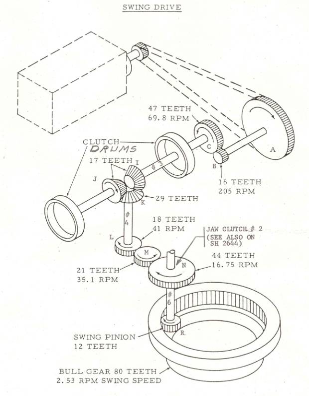
2. Swing operation for a standard lattice boom crane, crawler or truck crane:
All of the gears, sprockets, and shafts mounted on the equipment deck of the crane are called the draw works. The horizontal reverse clutches located in the draw works are used to swing the crane. Refer to the sketch below for the location of these clutches. The internal expanding bands (swing clutches) are not shown for clarity and only the clutch drums are shown connected to shaft No. 3. Shaft No. 3 is actually hollow and is made up of two sections. One section is connected to pinion gear “I” and a clutch drum and the other section connects to pinion gear “J”and the other clutch drum. These two sections of shaft only rotate when the crane swings. A second shaft is connected to sprocket “C” and runs thru both sections of shaft No. 3. The swing clutches are also connected to this second shaft. This means that this shaft and both swing clutches are rotating whenever the draw works are turning.
If the crane operator wants to swing to the left, he would move the swing lever until the left swing clutch starts to bear against and slip on the drum flange closest to sprocket “C”. He would continue to apply more pressure on the left swing clutch until less slippage occurres and the left clutch drum starts to rotate, which in turn rotates pinion gear “I” and on down thru the power train until the swing pinion “R” starts the crane swinging to the left. Note, as pinion gear “I” is turning counterclockwise, pinion gear “J” is turning clockwise. As the crane starts to swing faster, the operator would only keep enough pressure on the left swing clutch to keep the crane swinging at the speed he want to maintain. Note, that very seldom, does the operator actually apply enough pressure on a swing clutch to lock it to the drum flange. Most of the time, the swing clutches slip against the drum flanges to get the desired swing action. If he centers the swing lever, neither swing clutch is in contact with a drum flange and the crane would then just be “coasting”on its own. To stop the crane from swinging left, the operator would move the swing lever in the opposite direction and apply enough pressure with the right swing clutch until it slowly brings the crane to a stop. If the operator then wants to swing to the right, he would continue keeping pressure with the right swing clutch until the crane starts to slowly swing right. The main purpose of the above narrative is to show that swinging a crane is accomplished by playing one swing clutch against the other by slipping them against the appropriate drum flange. The swing clutches are never applied hard enough to stop the crane suddenly as this would side load the boom, rather the crane is always brought to a gentle stop before reversing it in the opposite direction.
Hydraulic cranes do not have horizontal reverse clutches; instead they swing by means of hydraulic swing motors hooked directly to swing pinions similar to “R”. Some hydraulic cranes are set up so that they will coast when the swing lever is centered. Most hydraulic cranes will not coast and to swing, the operator meters oil thru the hydraulic motors one way or the other. When the operator stops metering oil thru the hydraulic motors, they stops turning. Therefore, he has to be very gentle as he stops the flow of oil to the motors to keep from side loading the boom.
RIGGING ENGINEERING
ATTACHMENT DESIGN:
1. A safety factor of 1.8 is recommended for lifting attachment design. By using this factor and using the AISC allowables for stresses, the design will conform to ASME B30.20, “Below the hook lifting devices”.
2. Lug design for any lifting attachment must conform to AISC’s Part 5, specifications and codes, sections on pin-connected plates and eyebars.
3. A minimum safety factor of 1.25
should be used in analyzing vessel shell, skirt and basering stresses due to
lifting forces.
4. The allowable bending stress used in analyzing the above vessel stresses should not exceed .75*Fy.
5. In some cases, it is easier to initially draw a design to scale and show it the way it is supposed to look or fit up, and then go back and check it mathematically to ensure that it will work.
6. The design of some lifting attachments,
especially like a long spreader bar, should be limited by the amount of
deflection involved and not just the stresses involved. A long spreader bar can be designed so that
it is structurally sound but have visible deflection at the middle. In order to have the erection crew feel
comfortable with using the bar, the design should limit the deflection so that
it cannot be seen, even though the stresses may be very low.
7. Over the years, in checking
spreader bars designed with lugs top and bottom, it has been found that in most
cases the designers do not understand how to design them with the least amount
of bending, and the field is even worse in using them. And yet, most of
the spreader bars in use to day by the average contractor is this type of
bar. This type of bar is show in the sketch below.
To illustrate how critical the
design is, take the example of an 18" dia x 32’ STD wall pipe spreader bar
with the CG of the load at the center of the bar. The top lugs are not centered over the bottom lugs but are each
171.34” from the CG while each bottom lug is 180” from the CG. The centerline of the top lugs is 15” from
the centerline of the bar. With these
dimensions, and with the top slings at a 60 degree angle with the horizontal,
the line of force from the slings intersects the centerline of the bar exactly
over the bottom lugs. Therefore, the
bar will have zero bending from the influence of the slings. This bar will carry a 600 kip load based on
a combined unity stress check of 1.0.
If slings at 55 degrees are used, this bar will only handle a 325 kip
load. If slings at 70 degrees are used,
this bar will only handle a 440 kip load.
If the top lifting lugs were originally
located directly over the bottom lifting lugs, and with the slings at 60
degrees, this bar will only handle a 155 kip load.
Therefore, it can be seen that
if this type of bar is used, that it should be designed for zero moment due to
the influence of the slings, and a sling angle of 60 degrees is
recommended. Using the bar with slings
that produce sling angles greater or lesser than 60 degrees should be done only
after a through design check has been made.
As a last comment, the top lugs should never be located directly over
the bottom lugs if the design is to achieve maximum capacity of the spreader
bar.

CRANE SET UP:
1. Crane Leveling Procedure
a. Layout the crane mats on the lift pad constructed per the steps in the lift pad construction.
b. Walk the crane upon the mats and if possible, swing the counterweight around several times.
c. Using a four-foot carpenters level, check the level in both the longitudinal and transverse directions. Check the transverse direction by placing the carpenters level on the machinery deck between the boom foot pins. The bubble in the carpenters level should be fairly well centered between the marks, and not more than 1/8 “ out of level.
d. If the crane is out of level more than 1/8” in four feet, walk the crane back off the mats and place plywood under the track areas as required.
e. Walk the crane back upon the mats and recheck the level.
2. Crane Lift Pad Construction
In general, the lift pad under the crane mats should be constructed to the following requirements:
a. A levelness of ¾” in 30 ft.
b. The lift pad should extend 3 feet outside the crane mats in all directions.
c. Any down slopes connected to the lift pad should be at a 2:1 (Horizontal: Vertical) slope or flatter.
d. The lift pad should be constructed so that it is well drained.
e. The lift pad should be constructed to the required soil bearing capacity.
3. Crane Mats
It is recommended that crane mats be used under the tracks of the crane for the following conditions:
a. When the soil bearing pressure under the crane tracks exceeds the allowable soil bearing pressure.
b. When the load is greater than 75 % of the lifting capacity of the lift crane, even if the allowable soil bearing pressure is greater than the actual soil bearing pressure under the tracks.
c. When the load is greater than 60 % of the lifting capacity of the tail crane, even if the allowable soil bearing pressure is greater than the actual soil bearing pressure under the tracks.
4. The top layer of crane mats should be laid out perpendicular to the crane tracks.
5. The crane mats should be placed as close to each other as possible. Do not leave gaps between the crane mats and then fill the gaps with gravel.
6. The effective length of the crane mats extending past the ends of the tracks must be used in determining the crane mat requirements for the lift. Consult a Rigging Engineer if necessary.
7. Crane mats or wooden blocking used under the floats of truck cranes should have an area that is at least four times larger than the area of the floats. This mat area should be used over soil or concrete. For cranes larger than 100 tons, a soil bearing study should be made to ensure that the correct area of crane mats is used for the allowable soil bearing of the lift pad. This is especially true for capacity lifts.
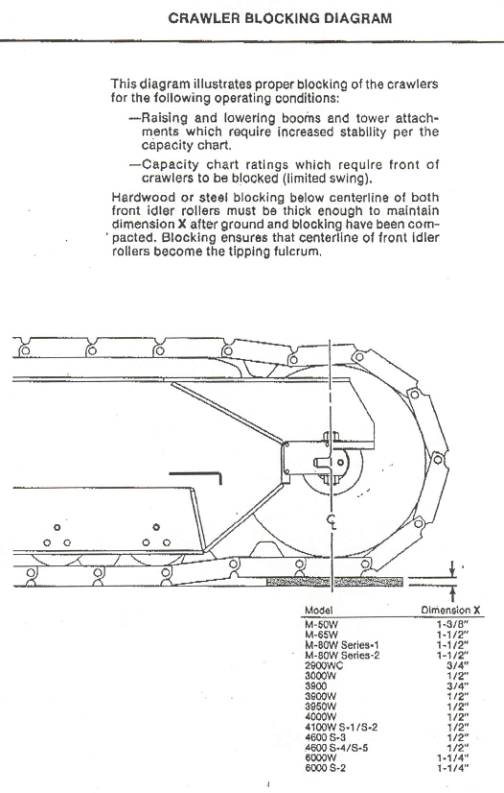
8. Blocking tumblers.
To correctly block the idler tumblers (the front tumblers), steel plate or hardwood blocking should be placed directly under the centerline of the idler tumblers and in a thickness recommended by the crane manufacturer. See the Manitowoc Engineering sketch below showing the correct location for blocking. The thickness of the blocking should range from about 1/2" to 1-3/8", depending on the crane manufacturer. The blocking width should be a maximum of 24" so it will not extend back under the front rollers. The length of the blocking should be equal to the width of the shoes + 12" (for a 6" extension either side of the track).
The following procedure should be used to block the idler tumblers:
a. Lay crane mats transverse to the
tracks.
b. Walk the crane upon the mats until it
is within the set radius for the lift
c. Set the travel locks on the crane
d. Walk the crane back against the travel
locks
e. Check the radius to make sure the
crane is still within the set radius
f. Mark the location of the centerline of
the idler tumblers on the crane mats
g. Walk the crane slightly forward until
the travel locks can be disengaged
h. Walk the crane backward about 5 feet
i. Place the steel plate or hard wood
blocking on the crane mats. Center the
blocking
so that there is 12" either side of the idler tumbler centerline mark on
the
crane mats.
j. Walk the crane forward until the
centerline of the idler tumblers is a few
inches past the
centerline of the blocking on the mats.
k. Engage the travel locks.
l. Walk the crane back against the
travel locks.
m. At this point, the centerline of the
idler tumblers and the centerline of the
blocking should coincide.
n. Recheck the radius
o. Make the lift.
Comments
on blocking tumblers.
a. To
correctly block the idler tumblers, the crane must be on mats, concrete,
etc. The tumblers cannot be blocked by
placing the blocking on soil, as the supporting surface must be strong enough
to transfer the fulcrum point from the center of the front rollers to the
center of the idler tumblers.
b. A certified
blocked tumbler lifting capacity chart must be used when lifting with the
tumblers blocked to get additional capacity above the regular lifting capacity
chart. Otherwise, use blocked tumblers
when lifting with a regular lifting capacity chart to provide added safety, not
to increase the lifting capacity.
c. Remember
that the lifting swing range for blocked tumbler ratings is over the front of
the tracks and within a projected centerline from each track.
CRANE STUDIES:
1. When doing a preliminary crane study, especially for a heavy lift, the following guidelines should be followed:
a. Use a maximum of 80% of lifting capacity chart for the crane being considered. Equipment to be erected has a habit of getting larger and heavier as it is being fabricated in the shop. Using 80% will provide some reserve capacity, just in case of growth.
b. In the elevation view of the crane study, use two (2) feet of clearance between the bottom of the boom and the spreader bar, the load, etc.
c. In the elevation view of the crane study, use five (5) feet of vertical clearance between the bottom of the load and the anchor bolts or support structure.
Using the design parameters above will provide some reserve capacity and clearances as the actual weight and size of the load and the plot plan are being finalized.
2. Design parameters for final design of an Engineered lift:
a. In general, use a maximum of 95% of the lifting capacity chart of the crane. For a lift to be made at 100% of the lifting capacity chart, the following factors must be considered:
1. The weight of the load must be know to +/- .5 %
2. The soil bearing pressure from the lift must be lower than the allowable soil bearing of the soil under the crane mats or concrete lift pad.
3. The crane must be set up solid and level.
4. The weather conditions must be clear and calm.
5. The lift must be made very slowly without any impact.
b. Use a minimum of one (1) foot of clearance between the boom and spreader bar, load, etc.
c. Use a minimum of three (3) feet of vertical clearance between the bottom of the load and the anchor bolts or support structure.
DEADMEN:
1. Buried deadmen should be used when every possible as they
are much safer than deadmen used on top of the ground. For example, using a coefficient of friction
between concrete and dry soil for sliding can quickly be reduced to a coefficient
of friction some where between concrete and ice if the weather turns cold or
rainy. Also, an impact loading can move
a deadman when it exceeds the sliding safety factor. If properly designed and backfilled, a buried deadman should
never move more than an 1/8” to ¼”.
2. Example of a deadman design:
a. Maximum tension in the guywire = 76 kips
b. Slope of the guywire = 20 degrees
c. Use a safety factor = 1.5
d. Use a line of action of the guywire force through the center
of pressure
e. Use 350-lbs/cu ft for equivalent fluid density (EFD) from the
soils report
f. Fp = force from the passive earth pressure acting at 1/3 of
the way from the base of the triangle
g. Water table is at grade.
h. Fb = buoyancy force
i. Neglect the one-foot of over burden
j. Neglect sliding friction between the deadman and the ground
k. Neglect negative pressure on the bottom and back face of the
deadman
l. Assume a deadman 8’ wide (w) x 8’ high (h) x 11’ long (L)
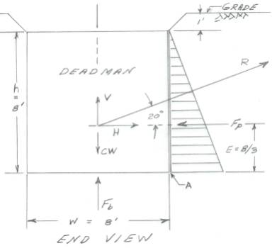 Refer to the sketch below:
R = 76* 1.5 = 114 kips
V = 38.99 kips
H = 107.12 kips
E = 8/3 = 2.67’
Check horizontal movement (sliding):
Resisting force Fp = EFD*L*h^2/2 = (350 lbs/ft^3)*11’*8^2/2
=123.20 kips
123.20 kips > 107.12 kips GOOD
Check up lift:
Up lift force = V + Fb =
38.99 kips + 8’*8’*11’*62.40 lbs/ft^3 =
82.92 kips
Resisting concrete weight
CW = 8’*8’*11’*150 lbs/ft^3 = 105.60 kips
105.60 kips > 82.82 kips GOOD
Check overturning at
point “A”:
Overturning moment = (Fb
+ V)*w/2 + H*E =
=
82.92*4 + 107.12*2.67 = 617.69 kip-ft
Resisting moment = Fp*E + 105.60*w/2 = 123.30*2.67 + 105.60*4 =
751.61 kips
751.61 kip-ft > 617.69 kip-ft GOOD
Summary:
The
8’wide x 8’ high x 11’ long deadman is adequate for a guyline tension of 76
kips where the water table is at grade or ground level.
GROUND BEARING PRESSURE:
1. Ground
bearing capacity boils down to a matter of how much settlement can be tolerated
for a lift and/or how much money it takes to make the risk acceptable, i.e. if
you wanted to be extremely safe, a reinforced concrete lift pad complete with piles
could be constructed at a huge cost. As
an alternative, the lift pad could be constructed of crushed rock overlaid with
crane mats at a much cheaper cost. The
reinforced concrete pad could be design to have negligible settlement and the
crushed rock and crane mat pad could be designed for acceptable settlements of
say .5”. If the lift was directly over
the front of the crane so that both tracks settled .5”, then the settlement
would not be a problem as the boom would not be side loaded. If the lift included picking and swinging 90
degrees, and the .5” of settlement followed the lift around, again the
settlement would not be a problem.
The
problem with settlement is when it is differential settlement. This causes side loading on the boom and
also impairs the smooth operation of the crane by having to swing up hill,
etc. Therefore, in most cases, the lift
pad has to be designed so that differential settlement is minimal. This doesn’t
mean using reinforced concrete lift pads either. It can usually be done with improving the strength of the lift
pad with crushed rock or limestone and using crane mats over it.
If the ground bearing capacity of the lift pad is
slightly below the ground bearing pressure caused by the lift, a failure of the
soil will not occur, just settlement.
For example, consider a lift with a ground bearing pressure of 5,000 psf
being made on a lift pad with a ground bearing capacity of say 4,000 psf. In this case, the lift pad will settle until
it picks up the required bearing area to support 5,000 psf and then the
settlement will stop. This is usually
what happens and nobody realizes that the settlement has taken place, even if
it causes some differential settlement with some side loading of the boom. That is unless it settles far enough to
cause an accident.
So,
in summation, ground-bearing capacity is really a matter of how much settlement
can be tolerated and if any differential settlement can be allowed.
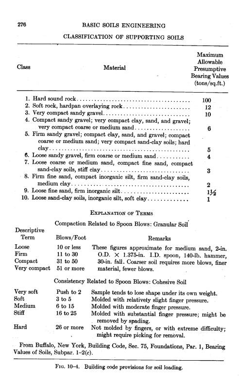
2. Figure 10-4
below shows some bearing values that can be used as guidelines when estimating
the bearing strength of a lift pad or the surrounding soil. Be very conservative in using the table,
i.e. if the lift pad and the subsoil are made of firm sandy gravel; choose
class 6 with a bearing value of 8,000 psf instead of class 5 with 10,000
psf. Whenever in doubt or for a very
critical lift, don’t guess. Have the
owner provide an allowable ground bearing capacity for the lift pad or sub soil.
HOOKS:
1. Load block hooks up to and including
250 ton capacity, should be completely disassembled from the load blocks,
thoroughly inspected, and repaired as required to bring them and any component
parts back to a like new condition.
This should be done at least every five years.
2. Overhaul ball hooks should be
completely disassembled from the overhaul balls, thoroughly inspected, and
repaired as required to bring them and any component parts back to a like new
condition. This should be done at least
every other year.
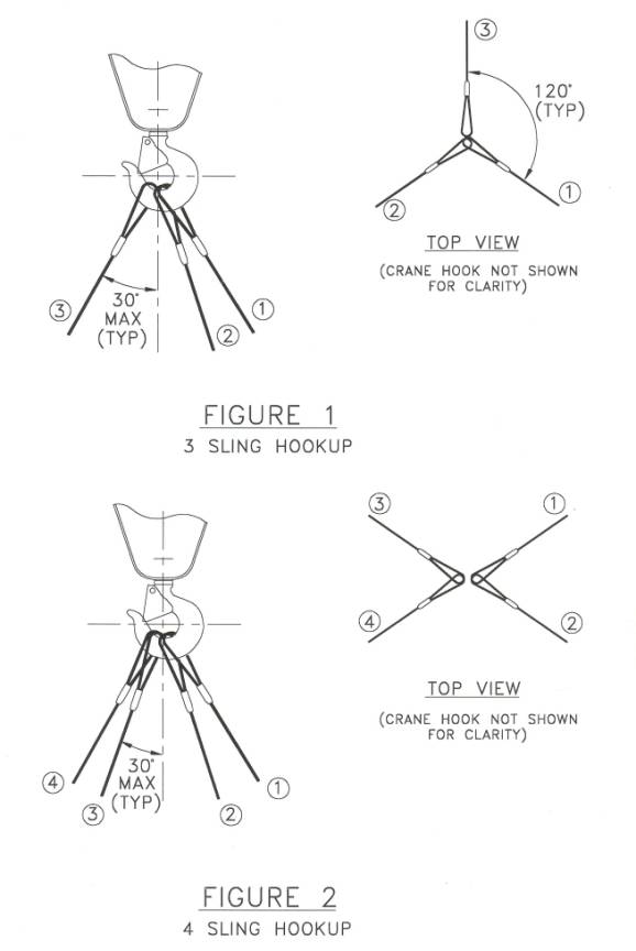
3. FOR ENGINEERED LIFTS ONLY, Crosby now
allows three (3) slings and four (4) slings to be collected in the bowl of a
Crosby Shank Hook with the following restrictions: (Refer to the sketch below for a graphic illustration of the
sling configurations)
a. All
legs must be collected within 30 degrees either side of the centerline of the
hook bowl as illustrated in Figure 1 and 2 of the sketch.
b. For
Three (3) Leg Slings:
1. The
vertical plane * of the hook should be parallel with the plane of the sheaves
2. The
horizontal sling angle of the legs must be 60 degrees or greater
3. The
single leg must be on the point side, and the double legs on the backside of
the hook throat
4. The
sum of the vertical components must not exceed the WLL of the system and/or the
hook
5. The
included angle between the sling legs must be 120 degrees as shown in the top
view of Figure 1
c. For
Four (4) Leg Slings:
1. All
legs must be loaded equally with symmetrical angles about the vertical
centerline of the hook
2. The
sum of the vertical components must not exceed the WLL of the system or the
hook
3. The
horizontal sling angle of the legs must be 60 degrees or greater
d. All
other loading conditions must be analyzed by a qualified person, and the WLL
reduced such that the combined hook shank stresses (bending & tensile) do
not exceed the original shank tensile stress at the rated WLL
* The
vertical plane bisects the hook through the centerline of the shank and point
4. When every possible, the hook
should be locked to the load block to prevent twisting up of the hoist lines
during lifting. Attach taglines to the
load to control rotation. If the orientation of the load to the boom at the
initial pick position (IPP) is not the same as at the set position, a quarter
back twist or forward twist of the hoist lines might be necessary to prevent
scrubbing of the lines during load lowering.
LIFTING:
1. I feel that the most important factors for making a
safe lift are:
a. Determine
a conservative weight of the load.
Include applicable weights of the jib, load block, overhaul ball, hoist
line, rigging gear, etc.
b. Set
the crane up solid and level.
c. Stay
within the lifting capacity chart of the crane for the configuration being
used.
d. Lift
only in weather conditions recommended by the crane manufacture.
e. Always
be conservative and do not reduce the planned safety factor of the lift. Always allow for the unexpected.
Other considerations for making a safe lift are:
a. Hold a
prelift meeting with everyone involved in the lift, including safety
representatives and client representatives.
b. Review
the checklist for the lift.
c. Explain
the duties of each member of the crew, i.e. who is in charge of the lift, who
signals the lift, etc.
d. Decide
on the method of communication, either visual hand signals or radio controlled,
etc.
e. Inspect
the rigging prior to the lift for damage and fit up.
f. Inspect
all lifting attachments prior to the lift to ensure that they have been
fabricated and connected to the load per the designers drawings.
g. Use
sling softeners between the slings and any sharp radii of the load.
h. Use
tag lines to control the load and keep workers away from the load. No one should touch the load until it has
been centered over and just above the anchor bolts or support, and where
applicable, has been secured against horizontal and vertical movement.
i. Use a
tape measure to layout the radius for the crane, do not step it off or use the
boom angle indicator. The boom angle
indicator should only be used as a reference.
j. Make
a dry run without the load to ensure the lift pad is level and there is
adequate clearance between the counterweight, the boom and adjacent structures.
k. Watch
for boom draw down as the crane takes the load. Boom draw down increase the radius of the crane and can result in
the load drifting away from the crane.
Boom up as required to maintain the planned lift radius before floating
the load.
l. On
critical lifts, such as upending a long heavy vertical vessel, use survey
equipment to track the boom tip through out the lift. Once the vessel is being upended, it is hard to tell just by
visually looking to know if the boom tip is at the planned radius. As the crane takes more and more of the
weight of the vessel, the operator can be directed to boom up as desired to maintain
the planned radius.
m. Use tie
back lines at initial pick between the crane and the load to prevent the load
from drifting away from the crane, especially of capacity lifts where an
increase in radius cannot be tolerated.
n. Use
caution when the lifting operation includes swinging with a load, especially
180 degrees. If the crane is not level
and swinging starts on the high side with the load positioned at a certain
radius, the radius will increase as the load swings to the low side of the
crane, possibly exceeding the maximum radius for the lift.
o. Instruct
the operator to engage the boom dog and release it only when booming down is
required.
p. Instruct
the operator to leave the house swing brake and/or lock off during lifting.
q. When
working with crawler cranes, added safety can be obtained by making all lifts
over the front of the tracks with the tumblers blocked. As the crane takes the weight of the load, a
qualified person, either the crane oiler or rigger, should constantly monitor
the track rollers on the counterweight side of the crane. If daylight occurs between the bottom of the
rollers and the top of the track shoes, or settlement occurs under the load
side of the tracks, the lift should be stopped and the lift conditions checked
as tipping may be starting
r. A
qualified person, either the crane oiler or rigger should constantly monitor
the outriggers as the truck crane takes the load. If daylight occurs between the top of the outrigger beams and the
outrigger housing on the counterweight side of the crane or settlement occurs
under the outriggers on the load side of the crane, the lift should be stopped
and the lift conditions checked as tipping may be starting.
s. A
qualified person, either the crane oiler or rigger should constantly monitor
the position of the load block during the lift by standing directly behind the
lattice boom crane and looking through the center of the boom, or by standing
behind and sighting on both sides of a hydraulic crane boom. If the load block
is not centered in the boom, the lift should be stopped and lift conditions
checked as the boom is being side loaded.
t. Whenever
possible, make a dry run with the load just clearing the ground. Swing the load over the side, for example,
and boom it out into a clear area to the actual set radius. Check the stability of the crane at the set
radius, boom the load into minimum radius, swing to the set angle over the rear
of the crane, boom out and set the load.
u. Do not
make any lift in winds that exceed the manufacturer’s recommendations.
v. If the
crane is working at minimum radius, boom down before releasing all the load
weight. Failure to do so will result in
bent boom stops and/or a bent boom as the stretch comes out of the boom
pendants.
The above list is not all-inclusive, but contains
the most important elements needed to make a safe lift. The rigging supervisor and the rigging crew
should also follow all good rigging practices and industry standards.
MODELS:
1. Models are very useful for determining how a load will
react during lifting. The model doesn’t
have to look exactly like the load being lifted; it only needs to be to some
scale with the weight, the location of the lifting points and the location of
the center of gravity in proportion to the actual load.
A
photo of a model of Quiz No. 1 is shown below.
Note that all that was required was a two foot piece of wood, two pieces
of bicycle chain and sprockets, a 1.5” nipple, a bolt, a nut, some washers and
some string.

TAILING A VERTICAL VESSEL:
1. For maximum safety during a tailing operation, the boom on the tail crane should be as short as possible. Many contractors try to get multi-use out of a crane, without changing the boom. The small expense of shortening the boom for a tailing operation and then lengthen it again is worth the added safety achieved.
2. Do not use a jib on the tail crane during a tailing operation. It is hard to keep the jib mast or the jib itself from interfering with platforms, etc.
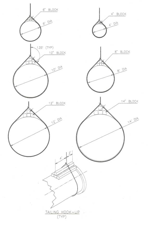
3. Vertical vessels that do not have tail lugs for up ending will have to be erected using a tail sling(s). There is some risk in this operation if the tail sling is not rigged properly around the skirt or bottom of the vessel. The correct procedure is:
a. Refer to the sketch at the bottom of this item and select
the recommended timber blocking size for the diameter of the vessel being
erected, i.e. for a 4' diameter vessel, use four- 4" x 4" x 6' hard
wood blocks.
b. Position the four blocks
on the skirt of the vessel as shown and secure them with two tirfors or
come-alongs.
c. Attach the tail sling to the hook on the tail crane.
d. Center the hook and tail sling over the vessel about 2' from
the base plate.
e. Wrap the tail sling around the skirt and connect it as shown
with the appropriate shackle.
f. Before tightening up the tail sling, rotate the sling
(clockwise as viewed on the sketch) around the skirt about 6". This will move the shackle off center and
force it and the sling to bite down on to the timbers as the sling is being
tightened up.
g. Snug up on the tail sling.
If the tail sling is not centered over the vessel, slack off on the
sling and repeat step f.
h. Hammer the shackle down as far as it will go until it rests
on the timbers.
i. Slowly hoist until the crane has about 50 % of the tail
load. If the sling and shackle are snug
down against the timbers and the sling is centered over the skirt, the bottom
of the vessel is ready to be lifted.
Note! If the sling and shackle are snug down against the timbers, it is nearly impossible for the sling to slip or ride up as the vessel is being up ended. In order for the sling to ride up on the skirt, the circumferential length of the sling around the skirt would have to increase. Under load, this is impossible. The friction between the sling /wood and the skirt provides a resisting force that is greater than necessary to prevent slippage of the sling.
4. Do not tail a vessel by placing a choker on a cone section. The sling will slip to the small diameter of the cone during lifting, possibly damaging the sling and/or flange.
TRANSPORTATION:
1. Transportation drawings should show the stability of the trailer and load for both tipping and structural. Calculations should be furnished that back up the above information. Allowable tipping should be calculated on a 5:1 safety factor. This is applicable to platform trailers and lowboys.
2. Transportation drawings for platform trailers should show how the hydraulic cylinders are plumbed, i.e., in a three-point suspension or in a four-point suspension.
WORK HABITS:
1. Work habits that have served me well during my career:
a. Carrying a notebook and keeping a to do list. Prioritizing it daily
b. Carrying a small tape measure and a piece of soap stone to the field
c. Keeping only one design job on my desk at a time
d. Breaking each job down and getting the long term items started first, so the job will come together as efficiently as possible
e. Always starting work on time. You can start work early, you can stay late, but people will always know if you are running late
f. Knowing that hindsight is always 20-20. Learning from my mistakes and then moving on, not dwelling on the mistakes
g. Keeping my employee’s from making the big mistakes, but letting them make the little ones by themselves, so they can learn and progress
h. Letting my employee’s know that if anything goes wrong, I will take the blame and when things go well, everybody will share the credit
i. Being loyal to the company and being honest. Never accepting more than a dinner from a Vendor
j. Being passionate about by work. I never had a day that I didn’t enjoy going to work.